


How to Create an Abrasive Blast Room
Want to create an Abrasive Blast Room? Abrasive blasting has been around for as long as man could throw a mineral abrasive, such as silica sand, onto an object. The reasons for the surface preparation vary from removing an existing coating to preparing the surface to accept a new layer. The idea is simple, and the industry was born with the advent of the air compressor.
An abrasive blast room is the core of any modern abrasive blast system. Confining the blasting operation to a controlled, clean environment enables efficient abrasive recycling.
The design criteria required for an appropriately sized blast room system include the size of the largest workpiece, the weight of the largest workpiece, the material handling method, the number of hours of blasting per day, and the base material of the workpiece. Each of these items needs to be addressed to finalize the blast room’s configuration.
The size of the most significant piece will determine the dimensions of the blast room enclosure. The room’s width is determined by adding four to five feet on each side of the workpiece. This space is required for the blast operator to maneuver around and blast the part from various angles.
The workpiece height also determines the size of the blast room, but the material handling of the part must also be considered. For example, if a work car on a track is the material handling method, the height of the work car must be regarded to determine the proper clearance of the blast room roof panels. Again, a four- to five-foot clear area will be required for the blast operator or up to seven feet if the operator walks on top of the part while blasting (e.g., a tank in the railcar industry).
The length of the blast room is determined by adding four to five feet on each end of the workpiece to allow for operator clearance.
Ventilating a blast room can be done by three different methods of air-flow design. The three air-flow designs are “down-draft,” “end-to-center,” and “cross-draft” ventilation.
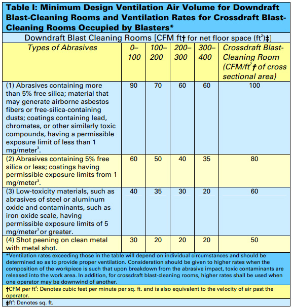
The various room air speeds are determined by the abrasive used in the blast room and the method the room is to be ventilated. Table I is provided by ANSI and outlined in ANSI Z9.4-1985, “Abrasive Blasting Operations–Ventilation and Safe Practices.”
The most common and economical method of ventilation is “cross-draft.” The calculation for the dust collector size is determined by the following formula: width of room x height of room x crossectional air speed (fpm) = cfm. Note: The cross-sectional airspeed is typically 50 fpm for steel grit abrasives and 60 fpm for nonferrous mineral abrasives.
For example, the dust collector sizing for a room 16 x 16 x 60 ft. that is using steel grit abrasive is calculated as follows: 16 x 16 ft. x 50 fpm = 12,800 cfm required for a room air-flow rate of 50 fpm.
The reclaim system adds air volume to the dust collector that will range between 500 to 1,200 cfm; therefore, the resultant dust collector will be sized for (12,800 cfm + 500 cfm.)—a total of 13,300 cfm.
When selecting the proper abrasive for the blast room, looking at the entire spectrum of parts that will be blasted in the facility is essential.
For example, a job shop blasting operation may see one type of work for some time and a different kind of fabricated aluminum parts for another period. In this application, you would want to select an abrasive applicable to both base material types, i.e., steel (ferrous) and aluminum (nonferrous), such as garnet, star blast, aluminum oxide, etc.
While a mineral abrasive gives you the flexibility to accept various work into your shop, it does break down much faster than a steel grit abrasive. Typically, you can recycle mineral abrasives about three to six times, based on operating pressures at the nozzle and the initial size and hardness of the abrasive.
Steel grit abrasive also comes in a variety of sizes and hardnesses. The typical recycle rate for steel grit (G-40) is 150 to 200 times. Again, this can vary based on the operating pressure at the nozzle.
Disposal costs of spent abrasives constitute a significant factor in abrasive selection. The amount of waste that must be removed is directly related to the recyclability of the specific abrasive and the volume of the used abrasive. This can result in a large quantity of waste material that must be dealt with regarding the “cost of disposal.” This cost will vary based on the blasting operation and coatings being removed.
If lead paint or zinc primer is removed, the disposal costs can be up to $500 per 55-gallon waste drum. The return on investment (ROI) for a blast room facility is the critical element when investing in a blast room facility.
Recycling abrasives and minimizing waste disposal costs are crucial in achieving a good ROI on capital purchases.
The reclaim system is comprised of a floor reclaim and an abrasive separator. The floor reclaim design can vary from straightforward “sweep-in” plans to “full” floor reclaims, which recover all the abrasive through a grated floor.
Reclaim designs vary based on the manufacturer and abrasive that is being reclaimed.
When a very light abrasive, such as tiny glass beads or fine aluminum oxide (i.e., 120 mesh or smaller), is used, the most common reclaim method is a vacuum floor and cyclone separator. This method is used in most hand cabinets that use suction or pressure blasting.
Single-screw partial reclaim system.

Single-screw partial reclaim system.
The most reliable and cost-effective method of reclaiming the floor is the mechanical screw floor with a belt and bucket elevator, rotary scalping drum, and air-wash separator. There are four different designs for a reclaimed floor. They are single screw, “H”-shaped, “U”-shaped, and total reclaim. The proper design selection is based on production needs and economic concerns. The following is a description and plan view drawing of each reclaimed floor design.
A single-screw partial reclaim system is the most economical floor design available. The system contains the major components found in reclaim systems, including metering shed plates; heavy-duty screw, belt, and bucket elevator; air wash separator; perforated plate rotary scalping drum separator; and abrasive storage hopper with a caged man ladder and handrail. This reclaim package can be expanded to an”H,” “U,” or full-floor reclaim design. This floor design is for low- to medium-production levels.
H-shaped partial reclaim system

The “H”-shaped partial reclaim system adds two longitudinal metered screw assemblies along each side wall of the blast room. The position of the screw assemblies allows the abrasive delivered from the blasting nozzle, which is either blown or rebounded off the work piece, to strike the side walls and fall into the screws, reclaiming approximately 60 to 90% of the blast media. The remaining abrasive on the floor is pushed into the screw assemblies at the end of the work shift. The screws are protected from an overload by metering shed plates. The “H”-shaped floor design is typically utilized in a “flow-thru” room configuration where heavy workpieces or material handling devices can drive into the room and position the workpiece on the steel-covered concrete floor between the screws. This floor design is best suited for medium to high production.
The “U”-shaped partial reclaim system adds two longitudinal metered screw assemblies along each side wall of the blast room and positions the cross screw along the back wall of the blast room. The part of the screw assemblies allows the abrasive delivered from the blasting nozzle, which is either blown or rebounded off the work piece, to strike the blast room’s side walls and back wall and fall into the reclaim system. A “U”-shaped floor design will reclaim 60 to 90% of the blast media. The remaining abrasive on the floor is pushed into the screw assemblies.
U-Shaped partial reclaim system

The screws are protected from an overload by metering shed plates. The “U”-shaped floor design is typically utilized in an “in–out” room configuration where heavy workpieces or material handling devices can drive into the room and position the workpiece on the steel-covered concrete floor. This floor design is best suited for medium to high production.
The full-floor reclaim system utilizes multiple screw assemblies to create a fully automatic abrasive reclaim floor system. All the abrasive that is blasted is returned to the separator system. The full-floor reclaim design requires that the material handling of the workpiece be intricately designed into the room’s configuration.
Material handling of the workpiece includes a work car/track system, an overhead monorail crane, an overhead bridge crane, or heavy-duty floor grating and support steel sized to allow a forklift to drive onto the reclaimed floor. The full-floor reclaim design can be used with any room configuration. This system is best suited for high-production requirements.
The partial floor reclaim systems will have an added “clean-up” cost associated with the ROI that must be calculated into the justification for capital expenditure. Choosing the right floor configuration to meet production and cost requirements will result in the quickest return on your investment.
The material handling method of moving the workpiece through your facility or just through the blast room must be considered so the room is designed for that specific handling device.
As mentioned earlier, the partial reclaim floor designs lend themselves to forklift trucks driving the workpiece directly into the blast room, such as construction equipment or trailers.
Full-floor reclaim system

The full-reclaim floor design can be configured for a work car track system, overhead monorail or bridge crane system, or a combination of both. The blast room configuration will vary based on your plant layout and the material handling method for the workpiece.
A “flow-thru” room configuration is designed for work to enter one end of the room and exit the room on the opposite end. This configuration is typically used for an “in-line” production flow of the workpieces.
A “flow-thru” design requires more floor space in your facility in that you typically allow for an in-bound and out-bound staging area before the following production phase, such as paint.
An “in–out” room configuration is designed for work to both enter and exit the same end of the blast room. This configuration is typically used because of space or production flow considerations. The blast room and paint booth are usually side-by-side. This configuration allows for both chambers to be presented the workpiece from various sources and directions while minimizing factory floor space requirements.
The abrasive blasting done in an eight-hour period and the number of blasters required for that production level is another factor that dictates a blast room design.
For example, suppose you operate with four blasters in an outdoor sandblasting operation. In that case, you will require a blast room with enough room, abrasive capacity, and reclaimed equipment to accommodate this production level.
The reclaim systems and room designs will vary in size and capacity based on production levels.
Conclusion
An adequately designed blast room facility will provide your company with the tools to meet the demands for a clean environment and provide a good ROI. Recycling blast abrasives saves money by reducing waste. The enclosed blast room saves money by allowing production to continue regardless of outdoor weather conditions.
By Eric G. Thomas
Eric. G. Thomas has been involved in the abrasive air blast industry since 1987 and oversaw the installation of over 1,500 air blast facilities.
Visit our Google Business Page.
